MSR for very low-field applications
The magnetically shielded room (MSR) for low-field applications is intended for experiments in ambient fields smaller than 50 nT. These include magnetic field sensor calibration, various physical experiments, simulating interplanetary/interstellar magnetic field conditions, or the monitoring of bio-magnetic signals (e.g. magnetocardiography and magnetoencephalography).
The exterior shield consists of a double layer of electrical steel (2 x 1 mm thick) and has on all faces direct current (DC) coil windings (vertical and north-south horizontal) to impart an anhysteretic remanent magnetisation (ARM). The interior shield is made of a single mu-metal layer (1 mm thick) and is equipped with active DC coils to compensate small static and dynamic residual fields (and linear field gradients) . The low-field MSR has internal dimensions of 3.81 x 3.05 x 2.15 m (L, W, H) and is oriented in an east-west direction (length). It contains no cables or installations, except those necessary for field compensation. Electricity, data cables and lighting can be brought inside using mobile devices.


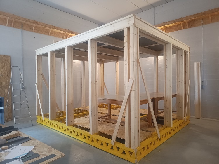
10. Done so far (August 2025): outer shield of the floor and ceiling are mounted, and corresponding ARM coils are installed.